Ladder logic programming is a method by which you can control machinery and equipment by utilizing a series of symbols and functions that fit together in a ladder-like diagram. It is often used in Programmable Logic Controllers (PLCs) to automate processes such as a factory or a building.
In ladder logic programming, each symbol is used for different function or operation. For instance, a contact symbol could correspond to an open or closed switch, and a coil symbol would represent something that could either be on (energized) or off. Programmers construct more complicated sequences of actions to control machines by linking these symbols together in a logical order.
Build a ladder logic diagram by first dragging input, output, and function symbols onto the page. The logical flow of the program by drawing lines on how each symbol is connected.
One of the key things that you need to be able to do when programming a PLC using ladder logic is troubleshooting and debugging your program. Some common troubleshooting techniques include:
Flexibility: Due to its use of simple symbols and functions for complex sequences of actions, ladder logic provides a great deal of flexibility in allowing programmers to tailor-control systems according to requirements.
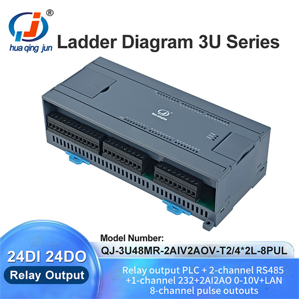
Due to its simplicity; Ladder Logic is used in Real-time monitoring: PLCs running Ladder Logic programs can usually be monitoried real time, allowing for easy debugging and troubleshooting the process without interrupting it. RS485 232 Ethernet Modules
Debugging tools – PLC programming software offers built-in debugging tools that allow better visualization of errors in ladder logic programs, and therefore make it easier to rectify them.

 EN
EN
 AR
AR BG
BG HR
HR CS
CS DA
DA NL
NL FI
FI FR
FR DE
DE HI
HI IT
IT JA
JA KO
KO NO
NO PL
PL PT
PT RO
RO RU
RU ES
ES SV
SV TL
TL ID
ID SR
SR SK
SK SL
SL UK
UK VI
VI SQ
SQ ET
ET GL
GL HU
HU TH
TH TR
TR GA
GA MK
MK HY
HY KA
KA BS
BS MN
MN