The relay ladder diagram is the most standard tool in industrial automation, Relays as such are used in many applications to control a circuit having one voltage by operating through another similar or lower power and this can be turned off or on the device like motor, valves, pumps etc. Content1 Introduction2 Construction3 Troubleshooting41 Very important thing in PLC ladder diagram relay before moving forward:> In the post we will discuss about basics of ladder diagram include details and then it is easy to trouble shoot upon that.
Step One: Inputs/Outputs; The initial of course is deciding what inputs to, from the devices you are trying to control.
Spring (Ladder diagrams): At this stage, Ladder diagram should be created which is a graphic representation of the relay circuit. This is a schematic diagram of the whole circuit that uses typical symbols to represent all of the devices and connections.
Logic; The last one is that you have to write the logic part on your ladder diagram. This is generally in the form of contacts and coils. The contacts break and make an electrical current, while the coils manipulate a magnetic field that commands motor operation
Finally Once logic is implemented, We should test the circuit in Bench Testing. The same is what a PLC simulator do,though you can see by your own eyes how an actualPLC behaves and the response of yur circuit to different inputs.
Here Are Some Tips in PLC Ladder Diagram Relay Circuits to Troubleshoot
This post covers some tips and trick so that you can save your time while debugging PLC ladder diagram relay circuits
Test Power & Connectivity - The power is turned on, so all devices in their respective circuit are also connected.
Is input signals valid - it should be check whether the input is correct
Consider debugging tools: If this is still the case, use a debug function to step line by line through code and find out at what point something goes wrong.
Circuit Simplification: We aim to dissolve a series connected large problem and identify that before...(Series Circuit -> easier testing)
Some Benefits of the PLC Ladder Diagram Relay You Can Consider For Your Industrial Applications
PLC ladder diagram relay circuits also enjoy many advantages in industrial automation.
Slide 16:These circuits can be designed in a config where you simply plug-and-play devices as required for your system - perfect if the process is dynamic Plug & Play (Dynamic) Flexibility.
Reliability: PLC ladder diagram relay circuits only have to be programmed and thoroughly tested once, following which they will typically work for years without failure; a virtue that is particularly important due to the intolerable nature of downtime in this type of application.
Several best practices, in turn will be useful when you design efficient and effective relay ladder circuits using PLC:
Design Initiation: Per the order of ICT aniering/ control and IO planning devices.
Deep Dive Testing:In this situation you should try to recognize and clear up potential troubles before implementation.
Standardized Symbols and Notation: it makes the documentation more clear to understand and easy for future adjustments.
Documentation Maintenance: Regular updates to your documentation will ensure that the problem can be quickly discovered and a full circuit matching an up-to-date change is exercised.
So, to sum up the PLC ladder diagram this relay will be found useless in industrial automation. In this way, you can implement a faithful ladder diagram circuits regulating your machines and processes by applying steps/practice we mentioned.
Building an imaginary PLC Ladder Diagram relay goes in the following sequence
Step One: Identifying Inputs and Outputs; The first step of course is determining the inputs to, and outputs from the devices you wish control.
Spring (Ladder diagrams): The next step is to create a ladder diagram, it used as graphical description of relay circuit. This diagram uses symbols to show the devices and connections of this circuit.
Logic: Lastly, logic needs to be added into the ladder diagram. This usually appears as contacts and coils. Contacts switch the flow of electrical current, while coils control a magnetic field that guides motor operation.
Bench Testing: The final step after integrating logic will be to test the circuit on bench. This can be achieved by using a PLC simulator which will behave just like how an actual PLC operates and you may see the response of your circuit to different inputs.
Here are few tips and trick so that you can save time while debugging PLC ladder diagram relay circuits:
Test Power and Connectivity: Make sure that the power is turned on, so all devices in their respective circuit are connected properly.
I Use Debugging Tools: If such is still the case, use debugging tools to detect where exactly a problem occurs by stepping through code line by line.
Circuit Simplification: While we dump a big problem connected in series, our aim is to break that relation and then identify earlier...(Series Circuit -> easier testing)
Here Are a Few Pros of the PLC Ladder Diagram Relay You Can Use In Your Industrial Applications
PLC ladder diagram relay circuits provide a number of benefits in industrial automation as well;
Simple to understand - The way logic is demonstrated, in a Ladder Diagram form.
Flexibility: These circuits can be configured in a way whereby devices are simply added/removed as needed, making them the ideal solution for dynamic processes.
Durability: PLC ladder diagram relay circuits only have to be programmed and thoroughly tested once, then they can work for years without any difficulties arising as well; a property invaluable in an application where downtime is often considered intolerable.
The design of an efficient and effective PLC ladder diagram relay circuits will benefit from several best practices:
Design Initiation: planning of the devices for control and IO's is an ICT process taken.
Testing in depth: Test thoroughly before implementing, attempt to identify and solve problems ahead of time.
Standardized Symbols and Notation: Use of standardized symbols and notation aid in comprehensibility as well as future readjustments.
Maintenance of Documentation: It is important to keep updating documentation regularly for troubleshooting future problems and checking proper circuit operation.
In a nutshell, the PLC ladder diagram relay proves to be of profane importance in industrial automation. By following the steps and practices we've outlined, you can create reliable ladder diagram circuits that regulate your machines and processes accurately.
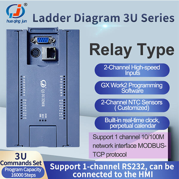
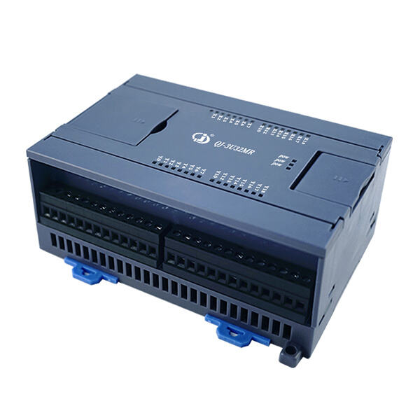
Huaqingjun, plc ladder diagram relay industrial control manufacturer. company, which has seen 20 years of expansion has grown become 3000sqms large-scale enterprise that focuses on the production, development sales Internet Things. We also have an R D department which can provide technical solutions customers. And our company has 4G module, Ethernet module, WIFI module, Bluetooth module, simple programmable PLC integrated machine RS485 communication module industrial relay module PLC AC/DC power amplifier module and other important products.
There variety applications consider parking system, greenhouse ETC induction system traffic lights system streetlamps control smart home systems water spray control, fire alarm system, HVAC SCADA, remote controls. There a myriad uses such as parking system. greenhouse, ETC Induction, packaging system. traffic lighting system. streetlamp control. smart home system. Robot control. water spray control. The plc ladder diagram relay line comes with an advanced SMT mounter, automated wave soldering, fully automated packaging machine a full collection high-quality inspection equipment to make sure that every product produced is "carefully skillfully created", that customers can buy use with confidence. We can also provide solutions specifically designed to our clients' requirements.
The company has number of national patents, and also has won awards like "National High-Tech Expertise" and "Guangdong Province Contract-abiding, Credit-abiding Enterprise". products have passed "IS09001 2015 Quality Certification". It also has CE, ROHS, FCC, SGS etc. certifications. company has also gathered many R D experts with degrees automation, electronics engineering, and communication engineering. experienced team devoted clients at the point of sale, continuously improves the plc ladder diagram relay of customers, and provides most Internet Things companies equipment manufacturing firms.
Patents have been granted our product development. The company won distinctions like "National High-Tech Expertise", "Guangdong Province Contract-abiding Enterprise" as well as "Creditworthy Enterprise". products have also passed "IS09001:2015 quality certification", plc ladder diagram relay the FCC, CE, ROHS, ISO other certifications. The company has assembled many experienced R D talents with professional academic background of electronic engineering, automation engineering communication engineering and so on. skilled team works closely with our customers daily basis, constantly improving the customer experience provides support to the majority of the equipment manufacturing enterprises. We design more competitive industry solutions customers. Furthermore, business boasts a sophisticated and efficient production facility. Each product is equipped with sturdy reliable chips that provide excellent performance. Customers can use purchase with confidence.

 EN
EN
 AR
AR BG
BG HR
HR CS
CS DA
DA NL
NL FI
FI FR
FR DE
DE HI
HI IT
IT JA
JA KO
KO NO
NO PL
PL PT
PT RO
RO RU
RU ES
ES SV
SV TL
TL ID
ID SR
SR SK
SK SL
SL UK
UK VI
VI SQ
SQ ET
ET GL
GL HU
HU TH
TH TR
TR GA
GA MK
MK HY
HY KA
KA BS
BS MN
MN