A ladder diagram resembles a ladder with two vertical rails and a number of horizontal rungs. Each rung is a different part of the program that instructs the PLC how to operate. For example, one rung instruct a PLC to turn on a motor when a sensor indicates something, and another rung may tell the PLC to stop the motor when a different sensor is tripped.
A good way to design an efficient plc ladder diagram is to divide your program into several fragments. Every part should map to a specific operation or task the PLC is required to execute. By structuring the program this way, error tracking and adjustments in the future will be easier.
Occasionally the best diagrams get a little wobbly. Typical problems can occur through incorrect wiring, damaged sensors or programming bugs. When you are checking for these problems, you will need to have a good idea of how the original ladder logic diagram is meant to operate.
A method of testing ladder logic circuit diagrams is known as debugging. This includes verifying each row of the ladder logic diagram to see that it is doing what it is intended to. Should a trouble be discovered, it's a simple matter to modify the wiring or code.
Advanced functions plc ladder diagram relay can also be used to implement such advanced functions as algorithmic or interfacing functions. For instance, commonly employed timers and counters are used to time the time of various functions or count the number of occurrences of a particular event.
Towards the realization of these advanced functions, more rungs may fill the ladder logic diagram. These rungs will include the instructions and requirements that the PLC must to complete the task. By cleverly arranging these rungs, the PLC can execute extraordinarily intricate sequences of operations efficiently.
One approach of the ladder diagram controller realization is to minimize the number of rungs and commands. The vector control, which uses PLC software, will enable quick information processing enabling faster response to inputs. It will also make the program easier to read and maintain, if you lay out the rungs in a consistent and sensible way.
The company has a range patent that are national in scope has also received honors such as "National High Technology Expertise" and "Guangdong Province Contract-abiding and a Credit-abiding enterprise". The products have been certified "IS09001 2015 Quality Certification". product has also received CE, ROHS, FCC, SGS etc. certifications. company has also gathered an impressive pool R D talent with academic backgrounds in automation, electronics engineering, and communication engineering. team is dedicated to serving the needs customers by improving customer service Ladder logic diagram of plc with the majority of Internet of Things and equipment manufacturing companies.
The product develop has been granted numerous patents. Our company has received distinctions like "National High-Tech Expertise", "Guangdong Province Contract-abiding Enterprise", and "Creditworthy Enterprise". The products have been accredited by the "IS09001-2015 quality certification" as well as other certifications such as FCC and CE. The company has brought together a number of R D talents who have academic degrees automation, electronic engineering communication, and many other fields. The team of professionals works closely with the customers enhance the overall experience of customers. They also service large Ladder logic diagram of plc of companies as well as manufacturers equipment. customers enjoy higher-quality solutions the industry. company has highly skilled efficient production facility. products are all equipped with reliable durable chips that ensure high-performance which allows customers to buy and use their products with confidence.
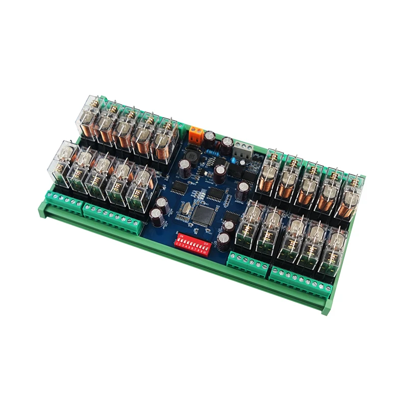
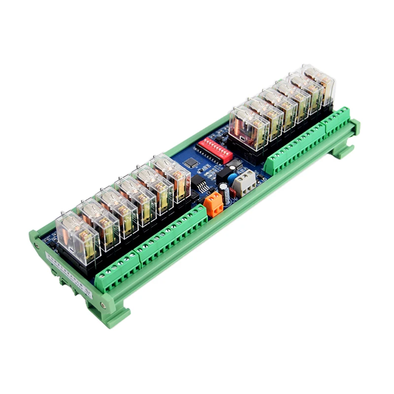
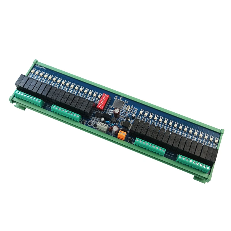
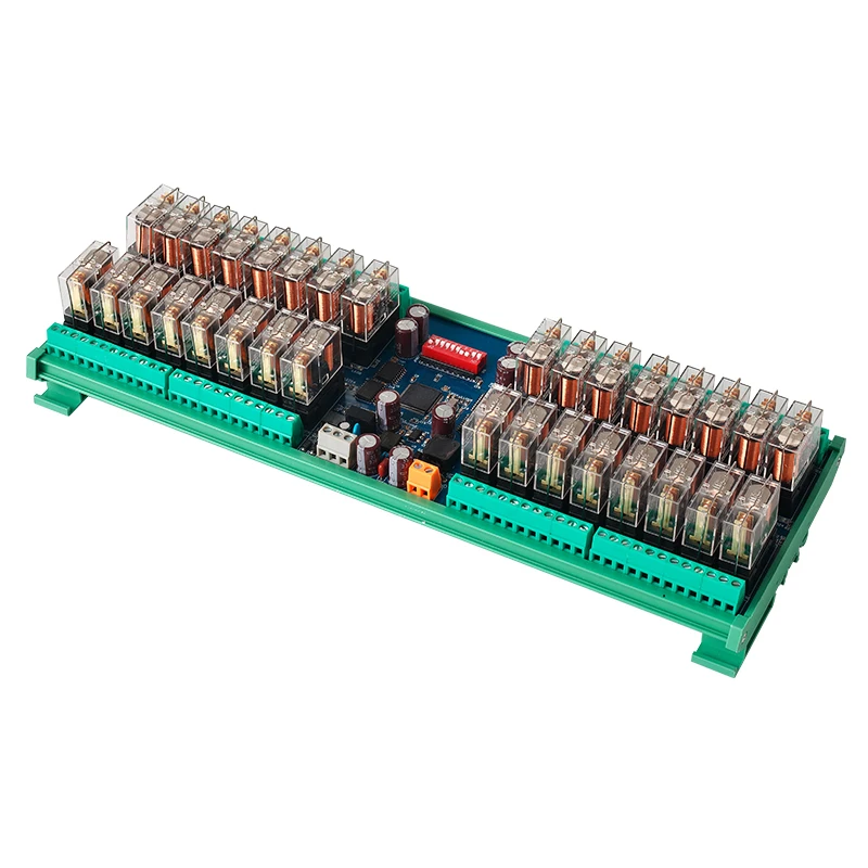
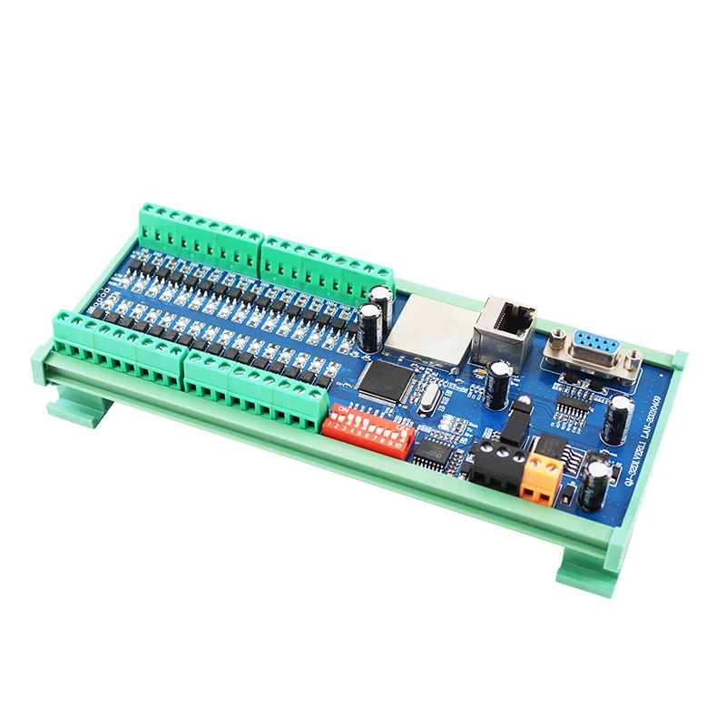
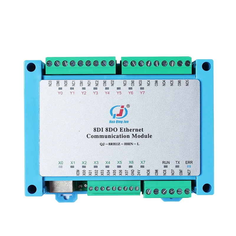
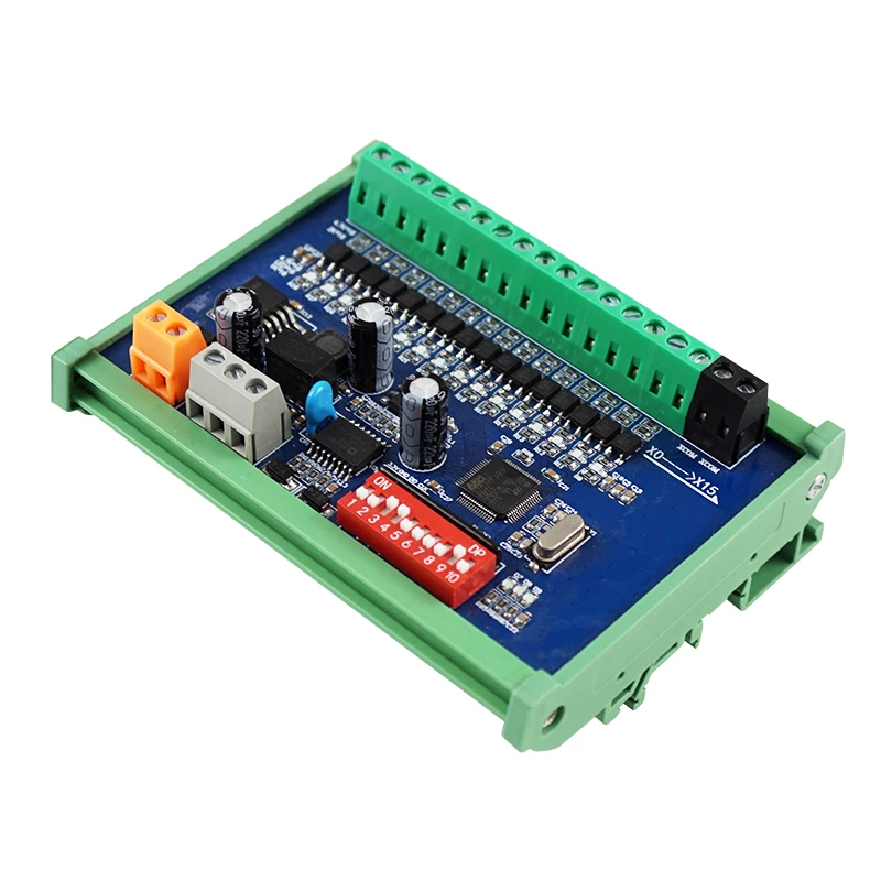
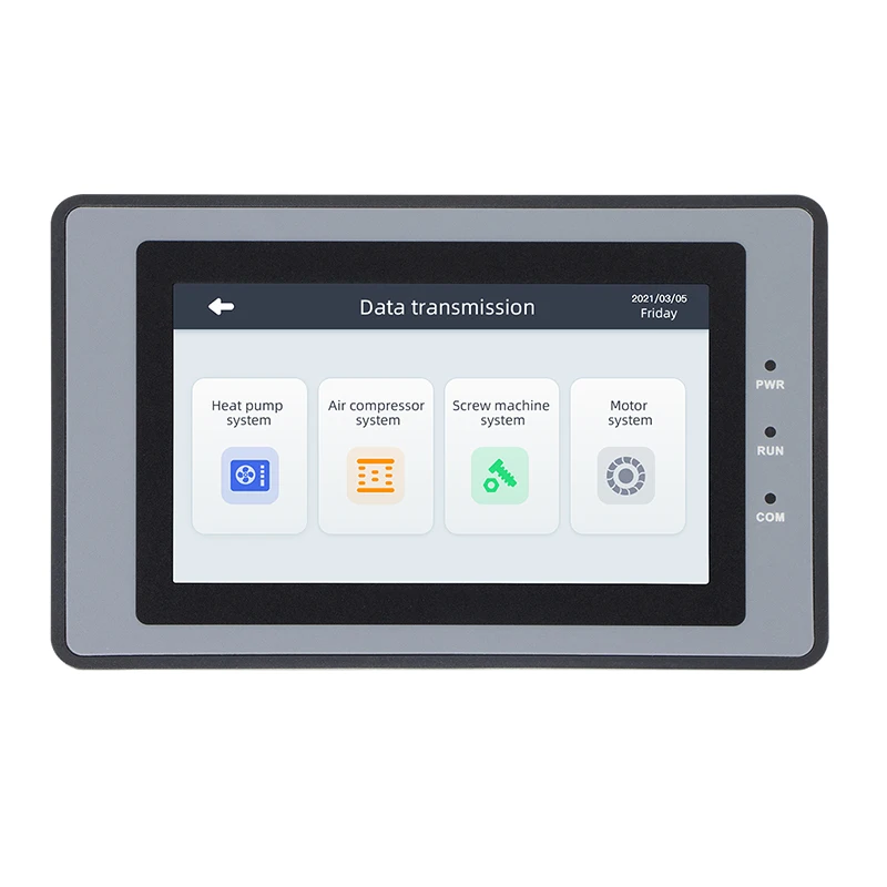
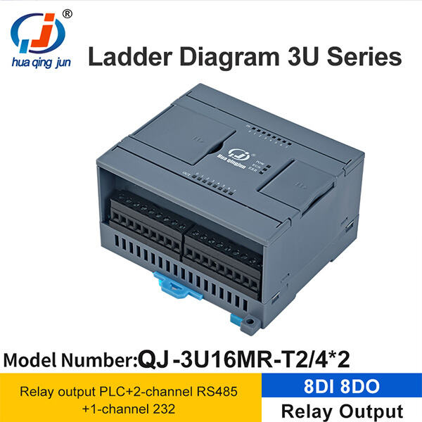
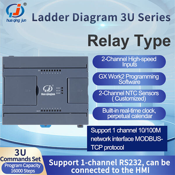
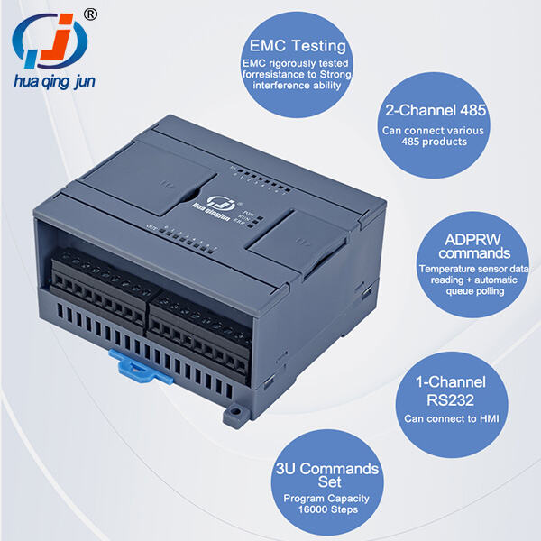
Huaqingjun a renowned manufacturing company industrial control. With over 20 years' experience, company has become as huge enterprise covering 3000 square meters that focuses on the creation, production and the sale of Internet of Things. Ladder logic diagram of plc has highly skilled R D department that can provide technical solutions our customers. Our company offers 4G modules, Ethernet modules, WIFI modules, Bluetooth Modules, Simple Programmable PLC Integrated Machines, RS485 Communication Modules Industrial Relay Modules PLC AC/DC Power Amplifier Modules as well as other core products.
products comprise RS485 The products of RS485 232 Ethernet modules and analog inputs modules PLC, analog outputs module, HMI, relay module, AC/DC amplifier board as well as switching power supply. There are numerous applications parking systems, such as. The greenhouse ETC Induction, packaging system. Ladder logic diagram of plc lighting system. streetlamp control. smart home system. Robot control. Control of water spray. The production line features SMT mounter equipped with automatic wave soldering automated packaging machines. The line also comes with complete set of quality control equipment. This ensures that each product is produced "carefully and professionally" to allow customers to buy and use the product with confidence. We are able to provide various options to meet the needs of the systems of our customers.
 EN
EN
 AR
AR BG
BG HR
HR CS
CS DA
DA NL
NL FI
FI FR
FR DE
DE HI
HI IT
IT JA
JA KO
KO NO
NO PL
PL PT
PT RO
RO RU
RU ES
ES SV
SV TL
TL ID
ID SR
SR SK
SK SL
SL UK
UK VI
VI SQ
SQ ET
ET GL
GL HU
HU TH
TH TR
TR GA
GA MK
MK HY
HY KA
KA BS
BS MN
MN